Sol - A 1kN Hybrid Rocket Engine
Sol is a 1kN Hybrid rocket engine designed as prerequisition and validaition to the specifications of an upcoming project, Kuiper.
Hybrid rocket engines have often been glanced over as an ineffective means of rocket propulsion and that is true in some cases. However, in small scale rockets and missiles, Hybrid Engines have been used to great success for many years due to their large safety margins and when designed well, performance characteristics in comparison to that of a solid engines at a similar scale. The throttleabilty and degree of control of a Hybrid Engine is one its largest advantages. Being able to stop and start an engine and control its thrust output provides the functionality of a liquid engine with the form factor of a solid engine, which is extremely useful in small scale applications.
Due to time and financial constraints, Sol is designed to be built with commercially available materials and relatively few custom built parts. Below is a cross-section of the complete engine assembly.
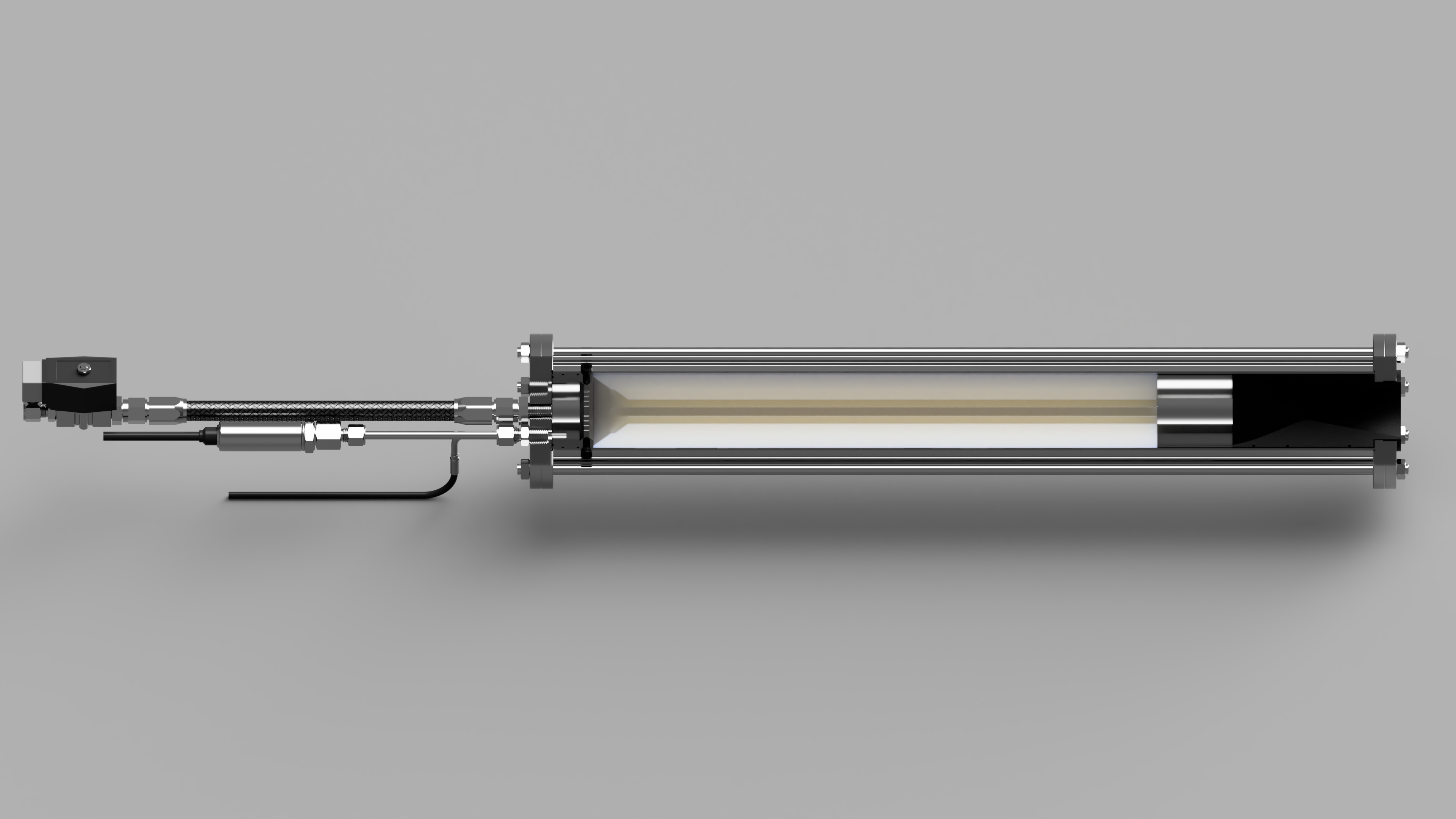
The engine is powered with an HTPB or ABS core and gaseous oxygen (GOx) oxidizer, designed for a nominal thrust output of 1kN at 300psi chamber pressure.
Specifications
Engine Design Specifications
- Thrust (Nomimal): 1 kN ~ 100 kg
- Chamber Pressure (Nomimal): 300 psi
- Specific Impulse (Opt): 238s
- Specific Impulse (Vac): 274s
- Expansion ratio: 4.04
- Throat Diameter: 21 mm
Propellant Specifications
- Oxidizer: Gaseous Oxygen (GOx)
- Fuel: Acrylonitrile Butadiene Styrene (ABS)
- Mixure Ratio (O/F): 1.0
Propellant Flow Characteristics
- Total mass flow rate: 0.42482 kg/s
- Oxidizer mass flow rate: 0.21334 kg/s
- Fuel mass flow rate: 0.21148 kg/s
Nozzle Geometery Efficiencies and Thrust Coefficient
- Divergence Efficiency: 0.99157
- Drag Efficiency: 0.96223
- Thrust Coefficient (vac): 1.59430
Nozzle Flow Model Specification
- Exit condition: 1 atm ~ 14.69 psi
The Nozzle
The nozzle geometry has been the most difficult part of this project so far, as achieving chocked flow at low pressure while aiming for high thrust output means making a visually displeasing nozzle and exauhst plume. As a result, I have chosen to slightly over-expand the nozzle, which will hopefully provide the optimal enviroment for the appearance of mach diamonds.
First iterations of the nozzle will be made with an SIC-based refractory concrete as it is relatively cheap and easy to mold using 3d printed negatives of the geometry. This makes it very easy to prototype and iterate quickly. However, there are some drawbacks to using refractory concrete such as particle ejection and structural stability at long periods under high pressure, therefore later iterations will be machined out of graphite rod.
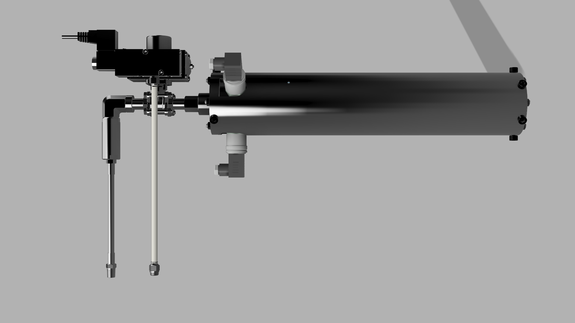
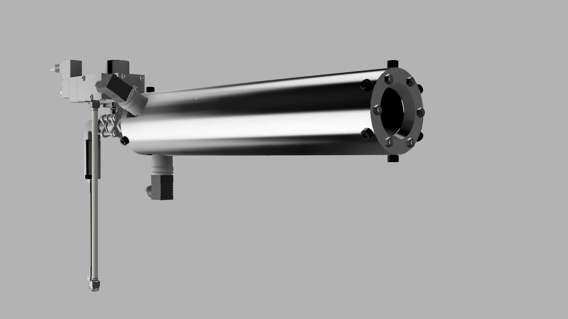
The Injector Assembly
Current renders of the assembly are out of date and have been redesigned multiple times, particularly the SH injector hole pattern. However, the general design remains true to the initial idea and that is a machined injector plate bolted through the side wall of the combustion chamber compressed against the oxidizer inlet plate using the eight retention rods on the outside to hold the injector plate in place. At the current design pressures the plate will hold and provide good distribution of the oxidizer. However, I'm unsure how well this will hold up at higher pressures.

The rear retention plate will be fitted with two pressure transmitters for redundancy purposes and a high temprature thermocouple. Although these measurements are not being taken directly inside the combustion chamber, I think that having sensors on the injector side will provide some valuble insight into how well the injector functions during operation. I have provided the part diagrams to give you an idea of how the engine is assembled and how it will function. Note that many issues have been found within the intricacies of this iteration.
Previous Iterations
Although these designs are out of date I think it is important to note the progression of the project, as the knowledge gained is more important than the final result.
Version 1 (Outdated)
The very first iteration of the engine was based around a large pneumatic operated actuator and designed to operate at 500psi for a nominal thrust output of 1kN. This design was good, however, was excessively expensive and would be difficult to machine many of the engines main components.